
- English
- Español
- Português
- русский
- Français
- 日本語
- Deutsch
- tiếng Việt
- Italiano
- Nederlands
- ภาษาไทย
- Polski
- 한국어
- Svenska
- magyar
- Malay
- বাংলা ভাষার
- Dansk
- Suomi
- हिन्दी
- Pilipino
- Türkçe
- Gaeilge
- العربية
- Indonesia
- Norsk
- تمل
- český
- ελληνικά
- український
- Javanese
- فارسی
- தமிழ்
- తెలుగు
- नेपाली
- Burmese
- български
- ລາວ
- Latine
- Қазақша
- Euskal
- Azərbaycan
- Slovenský jazyk
- Македонски
- Lietuvos
- Eesti Keel
- Română
- Slovenski
- मराठी
- Srpski језик
- Esperanto
- Afrikaans
- Català
- שפה עברית
- Cymraeg
- Galego
- Latviešu
- icelandic
- ייִדיש
- беларускі
- Hrvatski
- Kreyòl ayisyen
- Shqiptar
- Malti
- lugha ya Kiswahili
- አማርኛ
- Bosanski
- Frysk
- ភាសាខ្មែរ
- ქართული
- ગુજરાતી
- Hausa
- Кыргыз тили
- ಕನ್ನಡ
- Corsa
- Kurdî
- മലയാളം
- Maori
- Монгол хэл
- Hmong
- IsiXhosa
- Zulu
- Yoruba
- অসমীয়া
- ଓଡିଆ
- Punjabi
- پښتو
- Chichewa
- Samoa
- Sesotho
- සිංහල
- Gàidhlig
- Cebuano
- Somali
- Тоҷикӣ
- O'zbek
- Hawaiian
- سنڌي
- Shinra
- Հայերեն
- Igbo
- Sundanese
- Lëtzebuergesch
- Malagasy

How Flat Wire Rolling Mills Drive Improved Copper Wire Quality and Throughput
Drawing on 16 years of metal forming experience at Jiangsu Goodroller Machinery Co., Ltd. (GRM), this article examines how modern Flat Wire Rolling Mills — particularly modular Two-High and Four-High configurations — deliver measurable gains in copper flat wire quality and throughput. We cover the technical fundamentals, compare configurations in a structured table, share real-world application scenarios across transformer, photovoltaic, and EV motor sectors, and answer the questions manufacturers ask us most often.
Why Rolling Beats Drawing for Copper Flat Wire
I've spent over a decade watching copper flat wire producers wrestle with the same trade-off: drawing gives you shape, but it also gives you die wear, surface defects, and a ceiling on line speed. Rolling changes that equation. When you pass round copper wire through a series of precision roll stands instead of pulling it through dies, you eliminate die loss entirely and gain a level of dimensional control that drawing simply cannot match.
At GRM, we've been refining this approach since our origins as Zhangjiagang Hongxinyuan Technology in 2008. After a strategic restructuring in 2015, we doubled down on what we do best — designing intelligent precision rolling mills that solve real production bottlenecks. The Flat Wire Rolling Mills we build today are the result of that focus.
The core advantage is mechanical. Rolling deforms metal through compressive forces between rotating rolls, which means:
- No die wear. Roll life is measured in months, not shifts, and roll replacement is predictable rather than reactive.
- Better surface finish. Cold rolling produces a smoother, more uniform surface than drawing — critical for downstream enameling or plating.
- Higher line speeds. Without the friction and heat buildup of die drawing, you can push throughput significantly higher. Our integrated copper flat wire production lines reach design speeds of 400 m/min.
- Tighter tolerances. The combination of high-rigidity mill stands and online measurement feedback allows us to hold thickness tolerances as tight as ±0.005 mm.
In practice, I've seen customers cut their per-ton conversion costs by 15–25% simply by switching from a drawing-based flat wire process to an integrated rolling line. That's not a theoretical number — it comes from reduced tooling spend, fewer quality rejections, and faster cycle times.
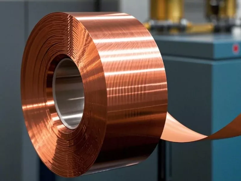
How a Flat Wire Rolling Mill Actually Works
People often ask me what actually happens inside a Flat Wire Rolling Mill. The principle is straightforward, but the engineering behind it is not.
A typical integrated line starts with a vertical coil payoff that feeds round copper wire — up to Ø8 mm in our standard configurations — into a multi-die drawing section. From there, the wire passes through a series of roll stands. Each stand reduces thickness and, when equipped with edging rolls, controls width. Between stands, online polishing and dust collection keep the surface clean. At the end, a laser-based thickness and width measurement system provides real-time feedback to the PLC, which automatically adjusts roll gaps to compensate for thermal expansion, roll wear, or incoming material variation.
Here's what that looks like in a typical GRM line configuration:
| Component | Specification | Quantity |
|---|---|---|
| Vertical Coil Payoff Stand | — | 1 set |
| Six-Die Drawing Machine | DLF6D/500 | 1 set |
| First Two-High Rolling Mill | Ø300 mm | 1 unit |
| First Edger Mill | Ø155 mm | 1 unit |
| Second Two-High Rolling Mill | Ø200 mm | 1 unit |
| Second Edger Mill | Ø155 mm | 1 unit |
| Third Two-High Rolling Mill | Ø160 mm | 1 unit |
| Online Polishing & Dust Collection | — | 1 set |
| Online Thickness & Width Measurement | Laser-based, closed-loop | 1 set |
| Transverse Take-Up Machine | Automatic winding | 1 set |
The line runs at a maximum design speed of 400 m/min and processes incoming wire up to Ø8 mm into finished flat wire with thickness ranging from 2.0–12 mm and width from 0.5–4.0 mm. For finer wire — think photovoltaic ribbon or precision micro flat wire — we configure a different setup with smaller roll diameters and higher speed ratios.
Two-High vs. Four-High: Choosing the Right Configuration
This is the question I get most often from production managers evaluating a new line. The short answer: it depends on your feedstock and your finished product requirements. The longer answer involves some practical engineering trade-offs.
Our Flat Wire Rolling Mills use a modular design that supports either Two-High Rolling Mill units or Four-High Rolling Mill units, and in many cases, a hybrid configuration works best.
| Parameter | Two-High Rolling Mill | Four-High Rolling Mill |
|---|---|---|
| Roll arrangement | Two work rolls, direct contact with material | Two work rolls + two back-up rolls |
| Typical work roll diameter | 160–300 mm (GRM standard range) | Smaller work rolls, larger back-up rolls |
| Reduction capability | Moderate per pass; ideal for roughing and intermediate passes | Higher reduction per pass; better for finishing and thin gauges |
| Dimensional accuracy | Good; ±0.01 mm width achievable with edger | Excellent; ±0.005 mm thickness achievable |
| Surface quality | Good for general flat wire | Superior; critical for enameling and plating |
| Typical application stage | Roughing and intermediate rolling | Finishing rolling, thin strip, high-aspect-ratio wire |
| Maintenance complexity | Lower; fewer rolls to manage | Higher; back-up roll maintenance required |
| Best suited for | Transformer conductors, CTC, larger cross-sections | EV hairpin wire, precision connectors, thin PV ribbon |
My rule of thumb: if your finished product is thicker than 3 mm or wider than 6 mm, start with a Two-High configuration for the bulk of the reduction, then add a Four-High finishing stand if you need tighter tolerances. For anything thinner — think EV hairpin conductors or fine photovoltaic ribbon — go Four-High from the finishing stage onward. The smaller work rolls in a Four-High mill exert higher contact pressure with less roll flattening, which is exactly what you need when you're chasing micron-level thickness control.
We've delivered both configurations to customers across electronics, appliance manufacturing, precision springs, and photovoltaic new energy sectors. The modular approach means a customer can start with a Two-High line and add Four-High stands later as their product mix evolves — without scrapping the entire investment.
Quality Gains You Can Measure
When I talk to quality managers, they don't want adjectives. They want numbers. So here's what our Flat Wire Rolling Mills actually deliver in production:
Thickness tolerance: ±0.005 mm on finished flat copper wire under stable conditions. That's roughly one-fifth the thickness of a human hair, held consistently over an entire coil.
Width tolerance: ±0.01 mm, managed by the edger mills that sit between the main rolling stands.
Straightness: The combination of short-stress-line roll design and precise tension control between stands produces flat wire with excellent straightness — critical for automated winding and downstream processing.
Surface finish: The online polishing and dust collection system removes rolling debris before it can embed in the surface. For customers who enamel or plate their flat wire, this translates directly into fewer coating defects and higher dielectric strength.
I should mention one more thing that doesn't always show up in spec sheets: consistency across the coil. It's one thing to hit ±0.005 mm on a test sample. It's another to hold that tolerance from the first meter to the last. The closed-loop control system — laser measurement feeding back to the PLC, which adjusts roll gaps in real time — is what makes that possible. We've had customers tell us their downstream rejection rates dropped by more than half after switching to a GRM line, simply because the dimensional variation from coil to coil went away.
Throughput Gains: Where the Speed Comes From
Speed is the headline number, but I want to be honest about where it actually comes from.
Our standard integrated copper flat wire line is rated for a maximum design speed of 400 m/min. Compare that to a typical die-drawing line running at 150–200 m/min for comparable cross-sections, and you're looking at roughly a 2× throughput advantage before you even factor in the elimination of die changes and the associated downtime.
But the real throughput story isn't just line speed. It's uptime and yield:
- Reduced manual handling. Because drawing, rolling, measurement, and take-up are integrated into one continuous process, there's no need to stop and move coils between stages. That alone can recover 2–3 hours of productive time per shift.
- Fewer unplanned stops. No dies to replace means no mid-coil interruptions for tooling changes. The roll gap adjustment is motorized and recipe-driven, so changeover between product sizes takes minutes rather than hours.
- Higher yield. Tighter tolerances mean less material goes to scrap. For a copper flat wire producer running 500 tons per month, reducing rejection from 3% to 1.5% saves roughly 7.5 tons of copper every month — a meaningful number at current copper prices.
- Automated take-up. The transverse take-up machine winds finished wire automatically, with consistent tension and no manual intervention. This reduces both labor cost and the risk of coil damage during handling.
In one recent project, a customer running transformer copper flat wire replaced two separate drawing lines with a single GRM integrated rolling line. Their monthly output went from 180 tons to 310 tons with the same headcount. The math on payback was under 18 months.
Application Snapshots: Where Our Mills Run
Our Flat Wire Rolling Mills are not a one-size-fits-all product. The modular design exists precisely because different industries have different demands. Here's a quick look at how the configuration changes across three key sectors:
| Industry | Typical Finished Flat Wire | Recommended Configuration | Key Quality Requirement |
|---|---|---|---|
| Transformer conductors | Thickness 2.0–12 mm; Width 0.5–4.0 mm | 5-stand Two-High + Edger | Dimensional consistency, electrical conductivity |
| Photovoltaic ribbon | Thickness 0.05–0.20 mm; Width 0.2–2.0 mm | Multi-stand Four-High | Thickness tolerance ≤ ±0.005 mm for uniform solderability |
| EV motor hairpin conductors | Thickness 1.0–3.0 mm; Width 3.0–8.0 mm | Two-High roughing + Four-High finishing | Edge contour, straightness for automated winding |
| Precision springs & connectors | Thickness 0.1–1.0 mm | Four-High with polishing | Surface finish, corner radius control |
The photovoltaic application is one where I've seen the tolerance requirement tighten dramatically over the past three years. As solar cell efficiency targets push higher, ribbon manufacturers are being asked to hold thickness variation within ±0.005 mm across the entire coil. The older drawing-based processes struggle with this because die wear changes the cross-section gradually over the coil length. Rolling, with closed-loop feedback, holds it stable.
For EV hairpin conductors, the challenge is different. You need a clean edge contour — the R-angle on the side of the flat wire has to be uniform, because any irregularity shows up as a weak point in the stator winding. We address this with dedicated edger mills and a finishing pass that specifically controls the corner geometry.
FAQ
What materials can a Flat Wire Rolling Mill process?
Our mills are primarily designed for copper and copper alloys, but the same platform handles aluminum, silver-plated copper, tin-plated copper, nickel-copper, and various alloy wires used in electrical and electronic applications. The roll material and surface treatment are selected based on the workpiece material to ensure consistent performance and roll life.
Can I start with a Two-High line and upgrade to Four-High later?
Yes. The modular design is intentional. Many of our customers begin with a Two-High roughing and intermediate line, then add Four-High finishing stands when their product mix shifts toward thinner or higher-precision flat wire. The control system and line layout are designed to accommodate this kind of phased expansion without requiring a full rebuild.
What is the typical lead time for a customized rolling line?
For a standard integrated copper flat wire line, we typically quote 4–6 months from order confirmation to factory acceptance testing. Custom configurations — particularly those involving non-standard roll diameters or specialized edging requirements — may extend that timeline by 4–8 weeks. We provide 3D production line modeling during the engineering phase so customers can review the layout and material flow before we cut metal.
How do you handle after-sales support for overseas customers?
We offer a global 48-hour response time for technical support and maintain a network of service engineers who can travel to customer sites for installation, commissioning, and troubleshooting. Remote diagnostics are available through the PLC control system for faster issue resolution. We also provide lifetime technical assistance for equipment we've delivered — we don't walk away after the warranty period.
Do you offer trial rolling or sample testing before purchase?
Yes. We encourage prospective customers to send us their incoming wire samples and target specifications. Our engineering team will run trial rolling on a comparable configuration in our test facility and provide a sample of finished flat wire with a full dimensional report. This gives both sides a clear, data-backed basis for the equipment specification.
If you're evaluating a Flat Wire Rolling Mill for copper flat wire production — whether for transformer conductors, photovoltaic ribbon, or EV motor hairpin wire — the technical team at GRM is available to discuss your specific feedstock, target tolerances, and throughput requirements. We've been building these systems since 2008, and we're comfortable with the hard questions.